- 您现在的位置:买卖IC网 > Sheet目录368 > W25X40BVZPIG (Winbond Electronics)IC SPI FLASH 4MBIT 8WSON
W25X10BV/20BV/40BV
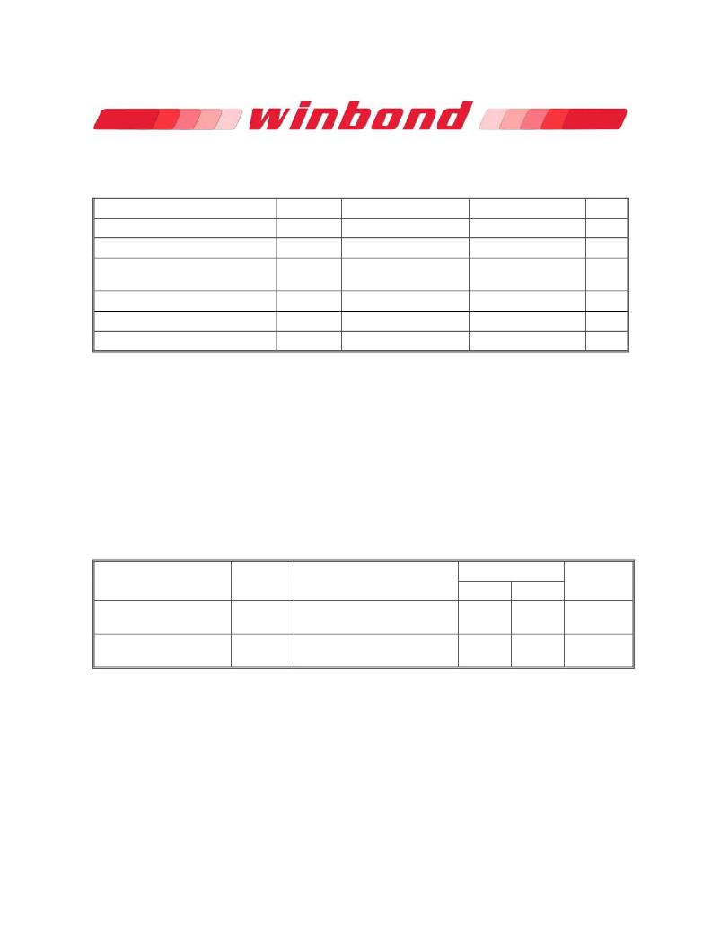
10. ELECTRICAL CHARACTERISTICS (1)
10.1 Absolute Maximum Ratings (2)
PARAMETERS
Supply Voltage
Voltage Applied to Any Pin
Transient Voltage on any Pin
Storage Temperature
Lead Temperature
SYMBOL
VCC
V IO
V IOT
T STG
T LEAD
CONDITIONS
Relative to Ground
<20nS Transient
Relative to Ground
RANGE
–0.6 to +4.0
–0.6 to VCC +0.4
–2.0V to VCC+2.0V
–65 to +150
See Note (3)
UNIT
V
V
V
° C
° C
Electrostatic Discharge Voltage
V ESD
Human Body
Model (4)
–2000 to +2000
V
Notes:
1. Specification for W25X10BV/20BV/40BV are preliminary. See preliminary designation at the end of
this document.
2. This device has been designed and tested for the specified operation ranges. Proper operation
outside of these levels is not guaranteed. Exposure to absolute maximum ratings may affect device
reliability. Exposure beyond absolute maximum ratings may cause permanent damage.
3. Compliant with JEDEC Standard J-STD-20C for small body Sn-Pb or Pb-free (Green) assembly
and the European directive on restrictions on hazardous substances (RoHS) 2002/95/EU.
4. JEDEC Std JESD22-A114A (C1=100 pF, R1=1500 ohms, R2=500 ohms).
10.2 Operating Ranges
PARAMETER
SYMBOL
CONDITIONS
SPEC
UNIT
MIN
MAX
Supply Voltage (1)
Ambient Temperature,
Operating
VCC
T A
F R = 80MHz, f R = 50MHz
F R = 104MHz, f R = 50MHz
Industrial
Commericial
2.7
3.0
–40
0
3.6
3.6
+85
+70
V
°C
Note:
1. VCC voltage during Read can operate across the min and max range but should not exceed ±10%
of the programming (erase/write) voltage.
Publication Release Date: August 20, 2009
- 37 -
Preliminary -- Revision B
发布紧急采购,3分钟左右您将得到回复。
相关PDF资料
W25X64VZEIG
IC FLASH 64MBIT 75MHZ 8WSON
W25X80AVDAIZ
IC FLASH 16MBIT 100MHZ 8DIP
W29GL032CB7A
IC FLASH 32MBIT 70NS 48TFBGA
W29GL064CB7S
IC FLASH 64MBIT 70NS 48TSOP
W29GL128CL9T
IC FLASH 128MBIT 90NS 56TSOP
W631GG6KB-15
IC DDR3 SDRAM 1GBIT 96WBGA
W9412G6IH-5
IC DDR-400 SDRAM 128MB 66TSSOPII
W9412G6JH-5I
IC DDR SDRAM 128MBIT 66TSOPII
相关代理商/技术参数
W25X40CLDAIG
制造商:Winbond Electronics Corp 功能描述:IC FLASH 4MBIT 104MHZ 制造商:Winbond Electronics Corp 功能描述:IC FLASH 4MBIT 104MHZ 8DIP
W25X40CLSNIG
功能描述:IC FLASH SPI 4MBIT 8SOIC RoHS:是 类别:集成电路 (IC) >> 存储器 系列:SpiFlash® 标准包装:2,000 系列:- 格式 - 存储器:RAM 存储器类型:SRAM - 异步 存储容量:256K (32K x 8) 速度:15ns 接口:并联 电源电压:3 V ~ 3.6 V 工作温度:-40°C ~ 85°C 封装/外壳:28-TSSOP(0.465",11.8mm 宽) 供应商设备封装:28-TSOP 包装:带卷 (TR) 其它名称:71V256SA15PZGI8
W25X40CLSNIG TR
制造商:Winbond Electronics Corp 功能描述:SPIFLASH, 4M-BIT, 4KB UNIFORM 制造商:Winbond Electronics Corp 功能描述:IC MEMORY 制造商:Winbond 功能描述:SPIFLASH, 4M-BIT, 4KB UNIFORM
W25X40CLSSIG
功能描述:IC FLASH SPI 4MBIT 8SOIC RoHS:是 类别:集成电路 (IC) >> 存储器 系列:SpiFlash® 标准包装:2,000 系列:- 格式 - 存储器:RAM 存储器类型:SRAM - 异步 存储容量:256K (32K x 8) 速度:15ns 接口:并联 电源电压:3 V ~ 3.6 V 工作温度:-40°C ~ 85°C 封装/外壳:28-TSSOP(0.465",11.8mm 宽) 供应商设备封装:28-TSOP 包装:带卷 (TR) 其它名称:71V256SA15PZGI8
W25X40CLUXIG TR
制造商:Winbond Electronics Corp 功能描述:NOT IN PRICE BOOK CONSULT FACT
W25X40CLZPIG
功能描述:IC FLASH SPI 4MBIT 8WSON RoHS:是 类别:集成电路 (IC) >> 存储器 系列:SpiFlash® 标准包装:2,000 系列:- 格式 - 存储器:RAM 存储器类型:SRAM - 异步 存储容量:256K (32K x 8) 速度:15ns 接口:并联 电源电压:3 V ~ 3.6 V 工作温度:-40°C ~ 85°C 封装/外壳:28-TSSOP(0.465",11.8mm 宽) 供应商设备封装:28-TSOP 包装:带卷 (TR) 其它名称:71V256SA15PZGI8
W25X40CVSSIG
功能描述:IC FLASH SPI 4MBIT 8SOIC RoHS:是 类别:集成电路 (IC) >> 存储器 系列:SpiFlash® 标准包装:150 系列:- 格式 - 存储器:EEPROMs - 串行 存储器类型:EEPROM 存储容量:4K (2 x 256 x 8) 速度:400kHz 接口:I²C,2 线串口 电源电压:2.5 V ~ 5.5 V 工作温度:-40°C ~ 85°C 封装/外壳:8-VFDFN 裸露焊盘 供应商设备封装:8-DFN(2x3) 包装:管件 产品目录页面:1445 (CN2011-ZH PDF)
W25X40L
制造商:WINBOND 制造商全称:Winbond 功能描述:1M-BIT, 2M-BIT, 4M-BIT AND 8M-BIT 2.5V SERIAL FLASH MEMORY WITH 4KB SECTORS AND DUAL OUTPUT SPI
